
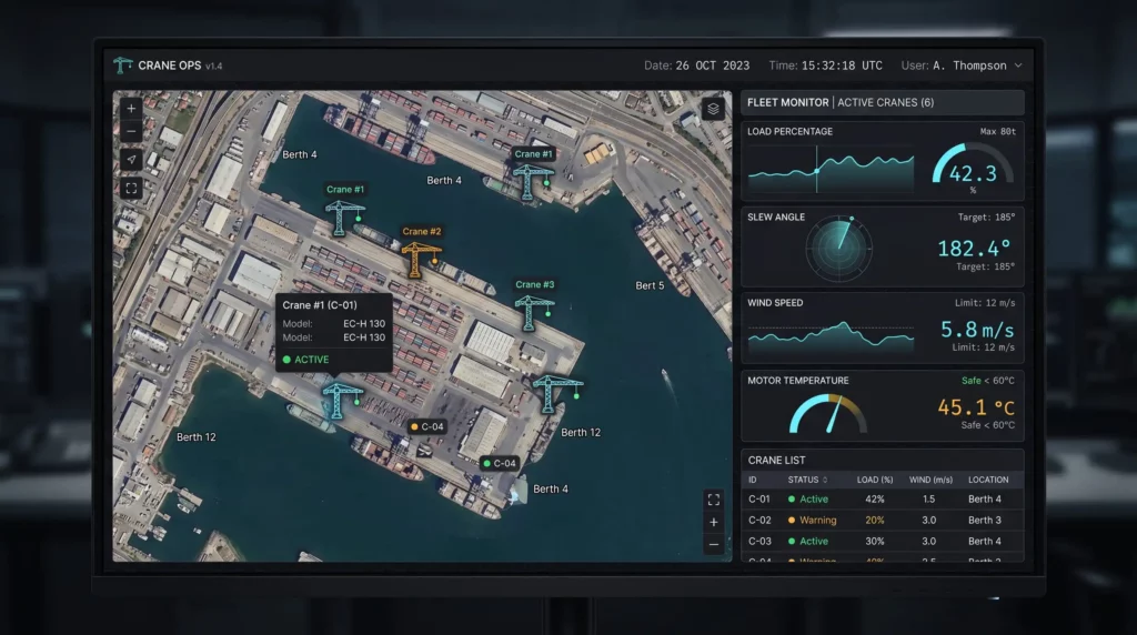
Walk onto any port, factory floor, or large construction site in 2026 and you will find cranes that are partially wireless and mostly not. The operator’s pendant talks to the crane on a licensed 433 MHz or 2.4 GHz link, usually a Cattron MGuard, an HBC Radiomatic Spectrum, or a Hetronic Nova. The fleet management system talks to a cellular gateway in the cabin. Everything in between, the boom sensors, the trolley I/O, the hoist encoder, the load pin, the slewing angle reference, the anemometer, the hook camera, runs on cable harnesses that have not fundamentally changed since the early 2000s.
That gap, between a wireless edge at the operator and a wireless edge at the cloud, is where the real industrial CAN bus problem lives.
A modern tower crane or large mobile crane runs CANopen with the CiA 417 lift control profile, or J1939 if the platform was derived from an off-highway vehicle. The bus is almost always a single backbone running from the cabin controller out to the boom tip and down through the trolley, with anywhere from twelve to thirty nodes hanging off it depending on the machine.
The problem is the physical layer, not protocol. CAN runs reliably at 250 kbps over a 250 meter cable and a tower crane at 80 meters is well inside that envelope. But the wiring has to be pulled through the lattice during commissioning, terminated correctly at both ends, and shielded from the EMI generated by every variable frequency drive on the same machine. When a sensor fails or a node is added, the rework is expensive, the operators often live with the gap rather than fix it.
A bus that lets you replace individual segments with reliable 200 meter line of sight wireless, without redesigning the protocol layer above, would change how cranes get retrofitted.
Three things tend to bite crane integrators after the design is locked.
The slip ring is the most common bus failure point on the entire machine. Every large crane has a slewing ring with a slip ring assembly that carries power and signal between the rotating upper structure and the static base. Anything that lets you put a bus controller on the boom side and run only power and an isolated wireless link across the slip ring, instead of running CAN signals through it, removes a maintenance headache nobody wants to own.
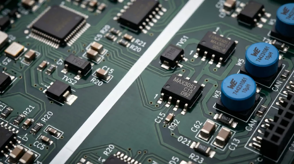
The 24V environment is harsher than the spec sheet suggests. Most crane systems are nominally 24V, but in practice you see transients from contactor switching, relay coils, and VFD bus pumping that go well above 36V on the rail. The board level needs ideal diode reverse polarity protection, transient suppression on the input, and real headroom on the regulators. A 9-36V input range covers the nominal case, but the protection circuits matter more than the range itself.
ESD and surge on the CAN Bus pair. A crane working outdoors in summer storms sees indirect lightning surge on every cable longer than ten meters. Automotive grade 24V working voltage TVS on the differential pair, combined with common mode chokes, is the difference between a unit that survives the season and one that does not.
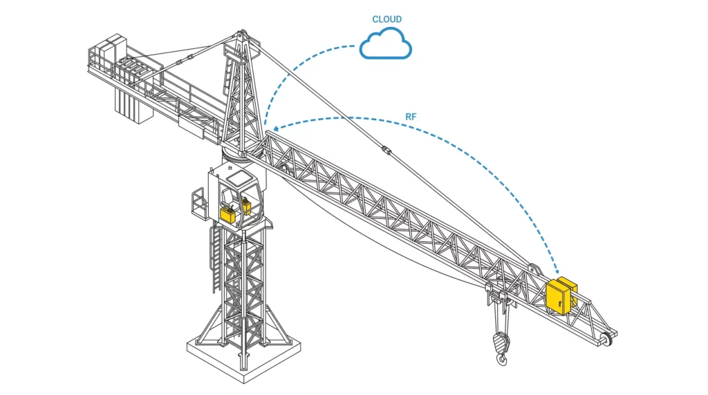
The interesting development in the last two years is ESP-NOW as a deterministic, sub 10 millisecond point to point link between two ESP32 radios on 2.4 GHz. ESP-NOW is not a Wi-Fi protocol in the TCP/IP sense. It is a connectionless layer that skips association and authentication overhead, which is exactly what makes it useful when you want something close to a wireless equivalent of a CAN segment.
Two ESP32-S3 modules on the same machine, one on the cabin controller and one on the boom tip, can carry CANopen frames across the slip ring at latencies that match the bus itself. That is the use case that justifies a dual wireless control board: one radio for low latency machine internal traffic via ESP-NOW, the other for 802.11 b/g/n Wi-Fi backhaul to a fleet management gateway.
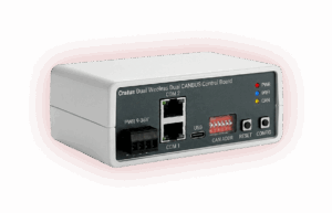
This is what the Cratus ASSET-Rx platform integrating INTERCAL8 ICL8-WC182 is built around. The ICL8-WC182 pairs an ARM Cortex-M7 running at 480 MHz with two CAN FD channels up to 2 Mbps, two independent ESP32-S3 modules, and a 2000 VDC isolated 24V rail rated to 20W for downstream sensor and actuator power, all in a single enclosure.
The other detail that matters on cranes specifically is wiring practice. Every additional connector on the bus is a failure point. The ICL8-WC182 uses dual RJ45 jacks that carry both power and CAN on the same cable, which lets an integrator daisy chain six or eight nodes along the boom without breaking out a separate power bus.
Each RJ45 carries V-IN on three pin pairs per side, each pair rated 1.5A. At 24V nominal that is roughly 100W of pass through capacity per port, plenty for a downstream node and its sensor loop.
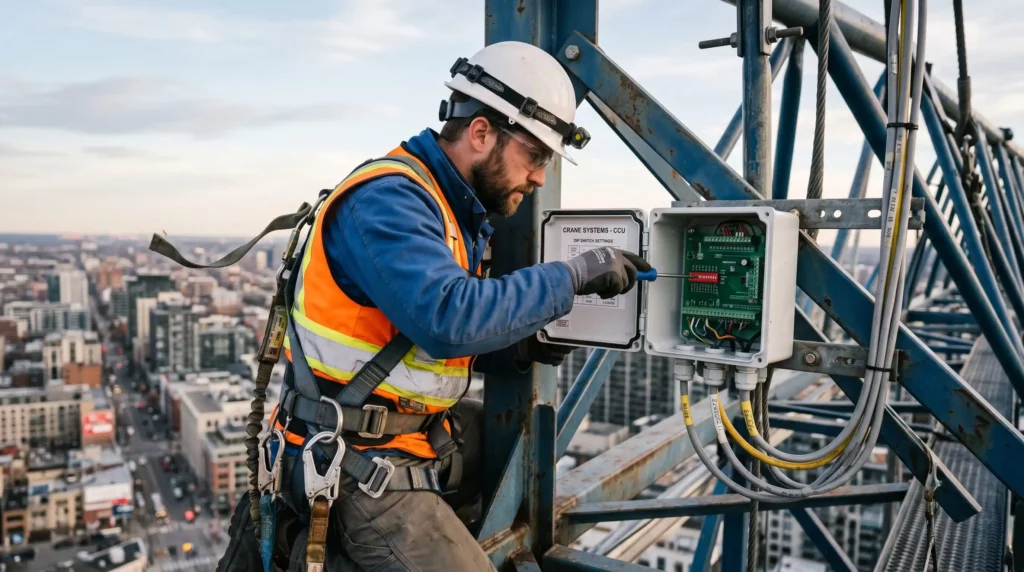
The address selection is the small detail that makes this work in the field. A 6 position DIP switch on each board gives 64 unique CAN node addresses without per device firmware. A maintenance technician at height in poor weather can swap a failed unit, set the DIPs to match the old node, and the system comes back without recompilation. That matters more than any specification on the ICL8-WC182 datasheet.
Two things to be clear about, because crane buyers will ask.
This is not a safety rated crane control element. ISO 13849 PLd or higher safety functions, overload prevention, anti two block, anti collision, slew limit, need a redundant safety bus and certified components, and a general purpose industrial control board running application firmware is not that. The right architecture is to keep the safety chain on a dedicated CAN segment with rated devices, and use a subsystem like this for non safety telemetry, condition monitoring, and configuration.
This is also not a replacement for the operator’s licensed band radio remote. Cattron, Hetronic, and HBC Radiomatic remotes use 400 to 900 MHz licensed or ISM bands precisely because 2.4 GHz is congested at any commercial site that has Wi-Fi. The dual wireless on the ICL8-WC182 is for machine internal links and cloud backhaul, not for operator joystick control.
The crane industry is moving toward predictive maintenance and remote diagnostics. Both are bottlenecked by how much data you can pull off the machine and how cheaply you can put a smart node on a sensor. A control board that combines CAN FD, dual wireless, isolated 24V power, and address selection in a single enclosure lowers the cost of placing a real node on every sensor that matters, which is what makes the data dense enough to do condition monitoring in the first place.
The question for crane OEMs and fleet operators in 2026 is not whether to instrument more of the machine. It is whether the bus and node hardware they specified five years ago can still carry what the next five years of telemetry will demand.
If you have run into the slip ring CAN Bus problem on a crane retrofit, or you solved the wireless segment replacement question a different way, we would be curious how you handled it. The CiA 417 community has been quiet on wireless extensions and there is a real conversation to be had there.
If you are designing or retrofitting a crane control system and the slip ring CAN Bus routing is on your problem list, we would like to talk. CRATUS is shipping INTERCAL8 ICL8-WC182 evaluation units (that either run on ASSET-Rx platform or standalone) to crane OEMs and integrators working on the wireless segment replacement architecture, and we are interested in the topologies you are seeing in the field. Reach out to [email protected] with your platform details and we will ship a unit, a technical brief on wireless timing characteristics across the slewing ring, and time on the calendar with our engineering team to walk through your specific bus layout.
Interested ?
We would be pleased to send you detailed information about our products or services.
Simply enter your details in the contact form below and we will get in touch with shortly.
CRATUS respects your personal information and keeps it safe. By sending this form, you consent to allow CRATUS to store and process your personal information as stated in our Privacy Policy.
CONTACT US / BUY
One of our experts will be communicating with you shortly. We are committed to understanding your application and providing support, tailored to your specific requirements.