

Why CAN Bus is Eating the AI Data Center From the Inside
Data center operators have spent thirty years not thinking about CAN Bus. BACnet for the building management system, Modbus for power monitoring, SNMP for the IT stack, IPMI and Redfish for server management. That has been the protocol stack since the late 1990s and most DCIM platforms, Vertiv Trellis, Schneider EcoStruxure IT, Nlyte, are still architected around it.
Then NVIDIA shipped a 120 kilowatt rack and the math changed.
The DGX GB200 NVL72 dissipates roughly 120 kW per rack with individual B200 GPUs running at 1000W TDP. Air cooling has a hard ceiling around 25 to 30 kW per rack, set by ASHRAE TC 9.9 thermal guidelines and basic fluid dynamics. Anything above that requires direct to chip liquid cooling, rear door heat exchangers, or full immersion. The infrastructure that delivers liquid to the rack, the coolant distribution units, the manifolds, the secondary loops, the leak detection sensors, did not come from the IT industry. It came from industrial process cooling, where CAN Bus has been the standard for two decades.
That is how CAN bus entered the AI data center. Not by design choice, but by supply chain.
Where CAN actually lives in modern DC infrastructure
Three places, growing fast.
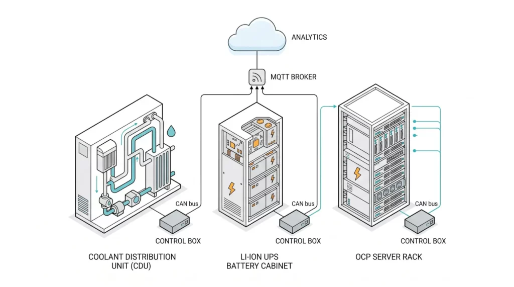
Coolant distribution units. CDUs from CoolIT, Motivair, Vertiv Liebert XDU, and Schneider Galaxy series almost universally use CANopen or J1939 internally for pump speed control, valve actuation, manifold pressure, supply and return temperatures, flow rates, and leak detection. The CDU exposes a Modbus TCP or BACnet IP interface upward to the BMS, but the internal sensor fabric is CAN. When something goes wrong below the Modbus abstraction layer, the diagnostic data lives on a bus the BMS cannot see.
Lithium ion UPS battery management. The shift from VRLA to Li-ion in data center UPS, driven by the same density and footprint pressures, brought CAN with it. Vertiv HPL, Schneider Galaxy VL, Eaton 9395 with lithium option, ABB DPA UPScale, all use an internal CAN bus to communicate cell voltage, temperature, state of charge, and balancing status from the cell modules to the cabinet controller. The thermal runaway risk profile of lithium chemistry makes that data operationally critical, not optional.
DC distribution at rack and row level. Open Compute Project rack designs run a 48V DC bus and increasingly use CAN for power shelf control, rectifier coordination, and battery backup unit telemetry. Hyperscalers running OCP fleets have CAN traffic on every rack whether they think about it or not.
Then NVIDIA shipped a 120 kilowatt rack and the math changed.
The DGX GB200 NVL72 dissipates roughly 120 kW per rack with individual B200 GPUs running at 1000W TDP. Air cooling has a hard ceiling around 25 to 30 kW per rack, set by ASHRAE TC 9.9 thermal guidelines and basic fluid dynamics. Anything above that requires direct to chip liquid cooling, rear door heat exchangers, or full immersion. The infrastructure that delivers liquid to the rack, the coolant distribution units, the manifolds, the secondary loops, the leak detection sensors, did not come from the IT industry. It came from industrial process cooling, where CAN Bus has been the standard for two decades.
That is how CAN bus entered the AI data center. Not by design choice, but by supply chain.
The integration problem nobody owns
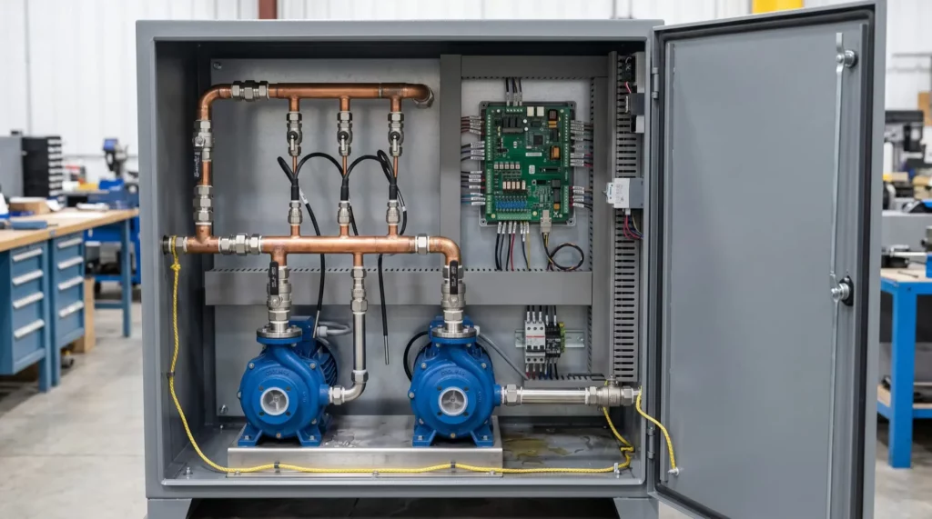
Each of these subsystems exposes a single upstream interface. The CDU has one Modbus TCP register map. The UPS has one BACnet IP integration. The OCP rack has a single rack management controller. That is fine for top level monitoring, but it loses the resolution that lives on the underlying CAN bus.
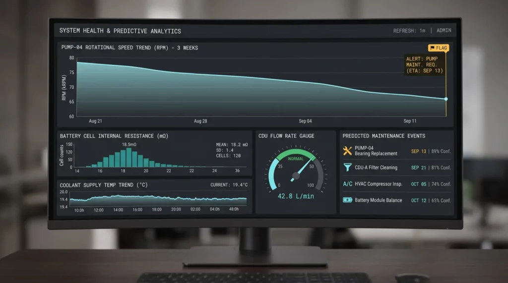
When a CDU pump starts running 4 percent slower than baseline, the CAN bus knows it three weeks before the Modbus alarm threshold trips. When one cell module in a 200 module Li-ion cabinet starts drifting on internal resistance, the CAN bus knows months before the cabinet flags a fault. That data exists, it is generated, it is visible inside the device, and it is invisible to the BMS by design.
Closing that gap is what brings a CAN bus aware control board into a data center conversation. Not as a replacement for the BMS, which is not the right architecture, but as a parallel telemetry plane that pulls the bus level data, processes it locally, and ships it to a separate analytics stack over MQTT, HTTPS, or whatever the operations team has standardized on.
What the architecture actually looks like
A control subsystem in this role sits between the CAN Bus of a target subsystem, a CDU, a UPS battery cabinet, an OCP power shelf, and the IP network of the facility. The hardware requirements are concrete and there is no slack on most of them.
Two independent CAN FD channels at 2 Mbps cover the case where a single board needs to listen to both the primary and redundant bus in an A and B redundant cooling system. Wi-Fi for the IP uplink is honestly the controversial part inside a hyperscale, where wired Ethernet is preferred for security and EMI reasons. For colocation facilities, edge sites, and retrofit projects where pulling new Cat6 to every rack is impractical, 802.11 b/g/n on 2.4 GHz remains the path of least resistance.
The INTERCAL8 ICL8-WC182 from CRATUS fits this role specifically. A Cortex-M7 at 480 MHz handles real time CAN frame parsing and local state estimation. Two ESP32-S3 modules give Wi-Fi for backhaul and a separate ESP-NOW radio for low latency board to board links, useful when two boards need to coordinate across a row without going through the access point. Two CAN FD channels per board cover the redundancy case. A 2000 VDC isolated 24V output rail powers downstream sensor nodes from the same drop.
The honest voltage range conversation
This is the place where a marketing sheet usually skips a paragraph. The ICL8-WC182 accepts 9 to 36V DC input, with an absolute maximum of 40V. That covers the 12V and 24V industrial cooling and instrumentation systems cleanly. It does not cover the 48V DC OCP rack bus directly. Connecting it across a 48V rail will exceed the maximum input rating and damage the input stage.
For OCP rack deployments, the practical answer is an upstream 48V to 24V step down converter (that can also be integrated in the enclosure while ordering units) feeding the V-IN terminal of ICL8-WC182. That is one extra component, but it lets the same board be specified across the whole facility, the cooling plant, the UPS room, and the rack level, with a single firmware base. That standardization is usually worth more than the bill of materials cost of one regulator.
ICL8-WC182 is genuinely a redundancy
This is not a BMS. BACnet IP, Modbus TCP, and the certified BMS integration paths exist for a reason and are not going away. The right architecture treats this subsystem as a parallel telemetry source feeding an analytics stack, sitting next to the BMS, not replacing it, but providing redundancy.
This is also not a fit for hyperscalers who have already standardized on a wired Ethernet sensor fabric. Meta, Google, and AWS have the in-house engineering capacity to design custom rack management controllers and they do. The deployment model where ICL8-WC182 subsystem makes economic sense is colocation operators, enterprise data centers running 5 to 50 megawatts, edge facilities, and AI factory build outs where the operator wants visibility into the cooling plant without commissioning a custom rack manager.
What changes for the operations team
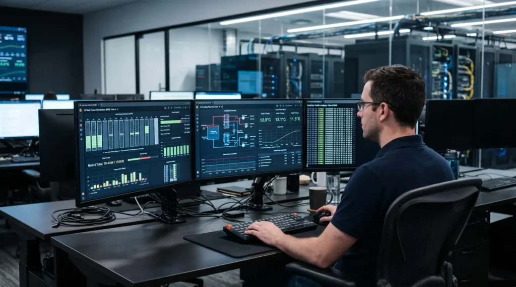
The practical effect of pulling CAN Bus level data into an analytics stack is that maintenance shifts from threshold based to trend based. A pump degrading 4 percent over three weeks is a maintenance ticket for next month, not an outage for tonight. A cell module drifting on internal resistance is a swap during scheduled downtime, not a thermal event during peak load.
That kind of predictive maintenance stack has been talked about in DCIM marketing for ten years. The reason it has not been delivered is that the data resolution at the BMS layer was never high enough to support it. Going one layer deeper, to the CAN bus that the equipment vendor already built into their product, is where the data actually lives.
The other place this matters is multi vendor cooling. A facility built out in three phases with CDUs from two different vendors and a Li-ion UPS from a third has three internal CAN dialects, three Modbus integration points, and no unified view. A control subsystem such as ICL8-WC182 that can attach to each subsystem’s CAN Bus and normalize the telemetry into a single MQTT topic structure does the integration work the BMS layer was never designed to do.
If you are running an AI training cluster or a colocation facility and have looked at the gap between what your CDU vendor’s Modbus map exposes and what is actually visible on the internal bus, we would be curious how you closed it. The vendor lock in on this layer is real and the workarounds vary widely.
If you are running a colocation facility, an AI training cluster, or an enterprise data center and the gap between your CDU vendor’s Modbus register map and the actual CAN telemetry inside the unit has become a maintenance problem, we want to hear about it. Cratus is working with several operators on parallel telemetry deployments using the ICL8-WC182, and we are ship evaluation units to teams piloting CAN level data extraction off CDUs, Li-ion UPS cabinets, and OCP power shelves. Email [email protected] with the subsystem you want to instrument and we will ship an ICL8-WC182 subsystem, integration documentation, and a sample MQTT schema we have been refining with the first wave of pilot sites.

Written by
Founder and CEO, CRATUS Technology, Inc.
Zeki founded CRATUS in 2013 and leads the San Jose team building LiDAR volume measurement systems, IoT sensing platforms, and energy and industrial automation hardware.
Full profileLinkedIn

Interested ?
We would be pleased to send you detailed information about our products or services.
Simply enter your details in the contact form below and we will get in touch with shortly.
CRATUS respects your personal information and keeps it safe. By sending this form, you consent to allow CRATUS to store and process your personal information as stated in our Privacy Policy.