
A wireless CAN bus bridge links two CAN (Controller Area Network) segments over a radio link. It receives complete CAN frames on one side, sends them over the air, and re-transmits them on the other side, so the two buses can exchange frames as if they were one network, with added delay. It is used where wiring is hard or unreliable: rotating joints, slip rings, mobile machines, cranes and retrofits.
This guide explains how a bridge works, what changes compared with a cable, and what to check in a design. For a ready-made option, see the CRATUS ICL8-WC182 Wireless Dual CAN Bus Bridge.
Why Bridge CAN Wirelessly?
CAN is a robust two-wire bus used in vehicles, machinery and industrial controls. Its weak point is often the cable. Wherever a machine moves, flexes or rotates, harnesses wear out, connectors loosen and routing becomes costly. A wireless bridge can replace just the segment that is hard to wire:
- Slip rings and rotating joints. Keep a power path across the joint and carry the CAN data on a radio link instead of through the ring.
- Cranes and heavy machinery. Boom, trolley and hoist nodes are far from the cabin controller. We describe this in Modern Cranes Have a Wireless Problem.
- Mobile platforms and robots. Articulated arms and moving carriages that would otherwise drag a cable chain.
- Retrofits. Adding a sensor node to an existing machine without pulling new cable through it.
- Telemetry. Reading CAN data from a machine and sending it to a gateway or the cloud.
We also covered this at Sensors Converge 2026. CAN is also spreading well beyond vehicles; see Why CAN Bus is Eating the AI Data Center From the Inside.
How a Wireless CAN Bridge Works
CAN is a broadcast-style bus. Every node can receive every frame, and each frame carries an identifier that sets its priority. When two nodes start sending at once, arbitration lets the frame with the higher priority win without losing data. A frame carries up to 8 data bytes in classical CAN and up to 64 in CAN FD (CAN with flexible data rate), and the receiving nodes acknowledge it in an acknowledge slot, according to Wikipedia.
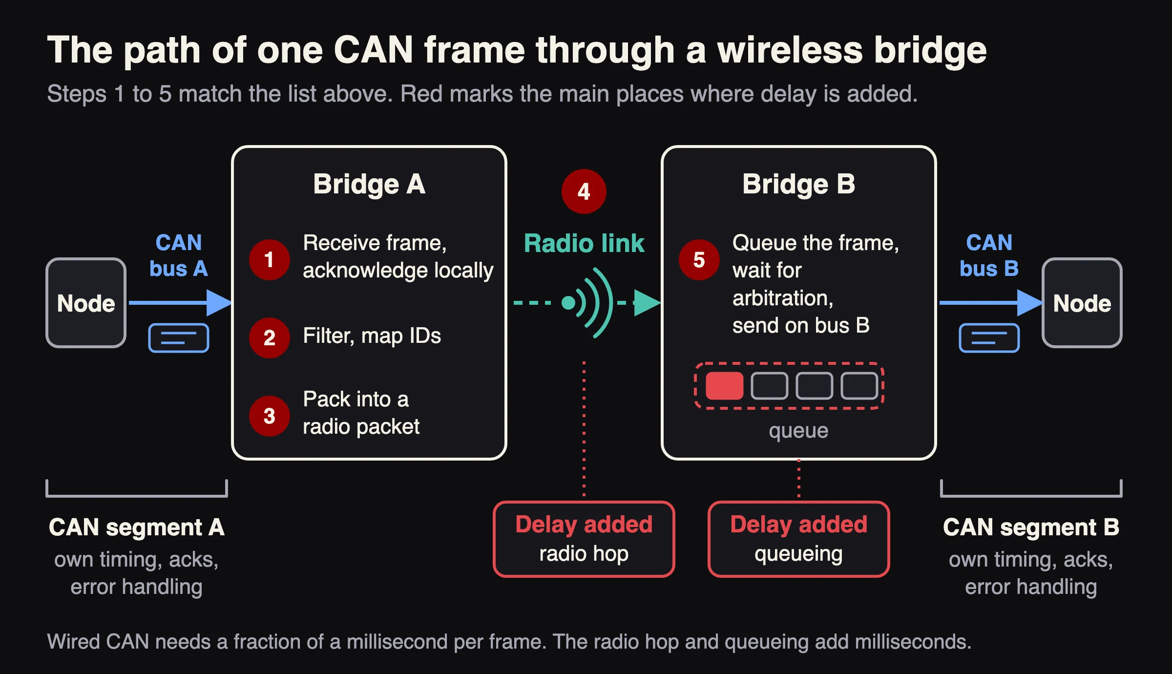
A bridge cannot pass these signals through a radio bit by bit. At 500 kbit/s one bit lasts 2 microseconds, and acknowledgment happens within the bit time, but a radio link takes milliseconds. So a bridge works at the frame level:
- The CAN controller on side A receives a complete frame and acknowledges it locally.
- The bridge applies filters and maps identifiers if configured.
- The frame is packed into a radio packet, often with other frames.
- The radio sends it to the bridge on side B.
- Side B queues the frame and transmits it onto its own CAN segment, competing in normal arbitration with the other nodes there.
Each side of the bridge is a separate CAN bus with its own timing, acknowledgments and error handling. The bridge does not make them one electrical bus. Because each side acknowledges frames locally, the sender on side A learns that the bridge received the frame, not that the far node did. A frame lost on the radio or dropped from a full queue can go unnoticed on both buses, so use message counters, heartbeat messages and timeouts in the application to detect loss. If you only need CAN data on a network, for example for telemetry, the far end can be a gateway that forwards frames to a Wi-Fi network or a cloud service instead of a second CAN segment.
What Changes Compared With a Cable
| Topic | Wired CAN | Wireless bridge |
|---|---|---|
| Latency | A fraction of a millisecond per frame (about 0.2 ms for an 8-byte frame at 500 kbit/s) | Adds milliseconds for the radio hop and queueing. Measure it on your own link. |
| Arbitration | One bus, one priority order | Priority is decided separately on each segment; across the link, frames wait in queues. |
| Bandwidth | CAN 2.0 up to 1 Mbit/s; CAN FD data phase up to 8 Mbit/s, or 5 Mbit/s with transceivers that meet ISO 11898-2 (the standard for the high-speed CAN physical layer). The arbitration phase runs slower. According to Wikipedia. | Limited by the radio and by how well frames are filtered and packed. |
| Reliability | Cable, termination and EMI (electromagnetic interference) | Radio range, interference, antenna placement and retries |
| Security | Physical access to the cable | Needs encryption and pairing on the air link |
| Installation | Wire to every node | Power and antennas at each end |
Radio Options
- Wi-Fi with an access point. Familiar and good for cloud connectivity, but adds the access point and network latency.
- ESP-NOW. A connectionless protocol on Wi-Fi hardware from Espressif. The ESP-IDF documentation lists a default bit rate of 1 Mbps, payloads of up to 250 bytes (version 1.0) or 1470 bytes (version 2.0), and optional encryption with CCMP (an AES-based mode). Point-to-point links avoid an access point. The bit rate is the rate on the air, not the throughput you can use. Compare the frame rate you must forward with the throughput measured on your own link.
- Proprietary radios. Chosen for range, frequency band or interference behavior in a specific site.
Design Checklist
- Bit rate and CAN FD. Confirm both segments run at the rates you need, and that the bridge supports CAN FD if your network does.
- Bus load. A 500 kbit/s bus can carry roughly 4,500 frames per second at 100% load for 8-byte frames with 11-bit identifiers (about 3,800 with 29-bit identifiers), before bit stuffing. Bit stuffing, the extra bits CAN inserts to keep the signal synchronized, lowers the real figure. Measure the real load, compare it with the throughput of your radio link and decide which IDs must cross the link.
- Filtering and ID mapping. Send only the frames the other side needs, and avoid ID clashes between segments.
- Loop prevention. With more than two bridges, make sure a frame cannot circulate.
- Packing. Combining several frames in one radio packet raises throughput, but adds delay.
- Latency budget. List the messages with deadlines and measure end-to-end delay under load and interference.
- Failure behavior. Decide what each side does when the link drops: hold, default values or a safe state.
- Lost frames. Decide how the application detects a missing message and what it does about it.
- Safety functions. Do not carry safety-critical messages over a wireless link unless a safety analysis covers it.
- Power and protection. Wide-range input, reverse-polarity protection, surge and ESD (electrostatic discharge) protection and isolation for the CAN pair.
- Security and updates. Encrypted pairing, and a way to update firmware in the field.
- Radio approval. A radio needs approval in every market where you sell the machine, in the United States from the Federal Communications Commission (FCC). A module or board that already carries approval reduces the testing, but ask what that approval covers.
Where a Wireless Bridge Fits
Good fits: telemetry and diagnostics, non-critical control, status and sensor data across rotating or moving joints, retrofits and temporary setups.
Needs careful analysis: control loops with tight deadlines, high-bus-load networks and anything where a lost or late frame could cause harm.
The CRATUS ICL8-WC182

The ICL8-WC182 is a Wireless Dual CAN Bus Bridge. According to the product page, one board combines two independent CAN FD channels, dual wireless links (Wi-Fi or proprietary wireless mode), a 9 to 36 V power input, 2000 VDC galvanic isolation, ESD protection and over-the-air firmware updates, and the CAN channels are listed as compliant with ISO 11898-2 (the standard for the high-speed CAN physical layer). The page lists CAN FD data rates up to 2 Mbps and classic CAN rates up to 1 Mbps, so compare those with the rates on your bus. The product page does not list ID filtering, frame packing or loop prevention. Ask us which of the checklist items the firmware covers and how many boards your layout needs. For more on where this helps, see our crane article. If you need a custom bridge or gateway, talk to us about electronic design and firmware development.

Sources
Last updated: November 16, 2026. Prepared by the CRATUS engineering team.
Frequently Asked Questions
What is a wireless CAN bus bridge?
It links two CAN segments over a radio link. Each side receives complete CAN frames and re-transmits them on the other side, so the two buses can exchange frames as if they were one network, with added delay.
Can CAN bus run over WiFi?
Yes, at the frame level. A bridge receives CAN frames, sends them over Wi-Fi or a similar radio, and re-transmits them on another CAN segment. It adds latency of milliseconds, so check it against your timing needs.
Does a wireless bridge support CAN FD?
Only if the bridge hardware and firmware do. CAN FD allows up to 64 data bytes per frame and faster data-phase rates, up to 8 Mbit/s according to Wikipedia, so confirm that the CAN controllers, the transceivers and the radio link can all carry your traffic. The ICL8-WC182 product page lists CAN FD data rates up to 2 Mbps.
How much latency does a wireless CAN bridge add?
It adds the radio hop and queueing, which is milliseconds, compared with the 0.1 to 1 ms a frame needs on a wired bus. The value depends on the radio, packet size, interference and bus load, so measure it on your own link.
Can a wireless CAN bridge replace a slip ring?
It can replace the signal channels of a slip ring for many non-critical signals. Power still has to cross the joint, so keep a power path such as a power-only slip ring. Safety-critical signals need a safety analysis before they go wireless.
How do you secure a wireless CAN link?
Use encrypted pairing on the radio link. For example, ESP-NOW supports encrypted unicast frames with CCMP when keys are set. Also limit which IDs cross the link and keep firmware updatable.